Implant Planning Using Ez3D-i and Ez3D Plus – #7 and #10
February 13, 2018
February 13, 2018

Case by Dr. Timothy Kosinski, Smile Creator Bingham Farms, MI
Pre and Post Surgical Script
:00 – Starting from the MPR window we can see the two eventual sites for teeth number 7 and number 10 in the 3D reconstruction window in the bottom right-hand corner.
:13 – Left click on the 3D pan icon tab along the top of the window where we can see our pan reconstruction at the top our Scout or axia view iin the bottom left as well as a sectional views in the bottom right-hand corner.
:20 – From here to left click on a navigation Pane and move it to site number 7 or we can also then England match the angle of an implant or in this case here parallel to are adjacent teeth numbers 6 and number 8.
:30 – I cannot navigate to the toolbar at the top and left click on the ruler and then measure from facial too powerful and then measure from the ridge up to the anomaly.
:45 – We then move the navigation pane over to site number 10 and and then left click to rotate the lines to match the angle of an implant or parallel to teeth numbers 9 and 11.
:60 – click on the ruler again and then measure in the sectional window the bottom from the facial to palatal and then from the ridge to the sinus floor.
1:10 – there is a shortcut feature whereby you can right-click on the vertical Dimension and then choose to place an implant if you’re not seeing the size implant in the shortcut list and also then left click on the insert implant icon in the upper left-hand corner of the software.
1:20 – from the implant property window we can first use or tooth number and then from there to the size along the right-hand side and put a check mark to place a crown and then left click on insert.
1:30 – once you place the implant you can reposition it in the second abused the bottom as well as rotate the implant around in the 3D pen reconstruction window at the top.
2:00 – we can then move our navigation pane over to site number 7 again. Select the insert implant icon along left hand side to the to open the implant property window , then scroll down to choose your implant size and then put a check-mark there for Crown as well and then select insert. Drop the implant in place and the sectional window in the bottom right-hand corner. Reposition in both the sectional window and 3D pen window as needed.
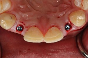
2:55 – post surgical placement assessment.
3:00 – we can then assess the placement of an implant in mpr window by adjusting or sagittal coronal and axial line as needed to verify placement between the two cortical plates as well as placement between existing teeth.
3:20 – now select a 3D pan tab on the top of the window and then assess the placement of our implants in the sectional windows in the bottom right-hand corner.
3:30 – slide the navigation pane over the implant site number 7 and adjust the angle to match the angle or implant and then use the sectional views to verify the angulation of the implant between the two cortical plates.
3:50 – Slide the navigation pane over to site number 10 to evaluate placement of the implant. Rotate the navigation pane to match the angle of the implant and then use the sectional views to verify the angulation between the two cortical plates as well
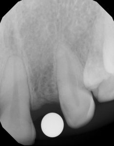
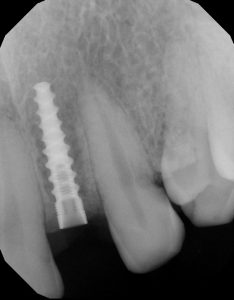
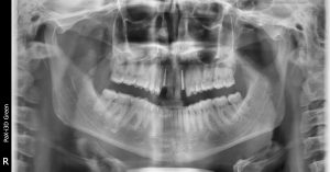
Radiology Report
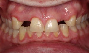
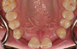
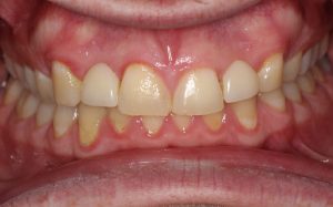
Clinical Photos


—
Ez3D Plus Treatment Planning
Narration: Lennart Elgaard, Education Manager, Vatech America, inc.
Timestamp Script:
0 – 0:18 – Introduction to the Ez3D software to identify the placement of our virtual Hahn implants in site number is 7 as well as site number 10.
0:18 – 0:37 – At this point we’re going to be working in a maxillary arch, so we’re going to construct our 2D pan curve by moving our axial line to the ridge in a coronal view and then in the sagittal you were going to compensate for the angle of our occlusal plane by moving the axial, so that it is parallel to the ridge or to the occlusal plane.
0:37 – 1:01 – We’ll then construct our 2D pan reconstruction which will also generate our sectional views by left clicking the icon for a panorama curve and then we’ll start in the axial window with the distal edge of the right molar and digitize our landmarks approximately 1 centimeter apart and in between the two cortical plates until we get to the distal edge of the molar on the left hand side of the anatomical arch.
1:01 – 1:24 – We have our 2D pan reconstruction in the bottom left hand pane, the sectional views show us our bone width as well as our bone height. The axial view will identify the location of each sectional view.
1:24 – 1:57 – We can measure our occlusal spacing between number 6 and 8 as well as between 9 and 11 if you wish to verify the amount of space that we have available for our two virtual implants. We can start by expanding our to 2D pan reconstruction. From there we can navigate to the measurement icon in the upper left hand corner left again and then measure the distance from the mesial edge of tooth number 6 to the distal edge of tooth number 8. This measurement gives us a distance of approximately 7 millimeters.
We can then measure the occlusal spacing for site number 10 by measuring from the distal edge of number 9 to the mesial edge of tooth number 11. This also gives us a distance of approximately 7 millimeters again.
1:58 – 2:30 – We can also measure our occlusal spacing by using our sectional views as well. Knowing that our intervals are one millimeter apart we can essentially use the section sectional views as ruler to measure from the mesial edge of number 6 to the distal edge of tooth number 8. To do this we move our sectional line in the 2D pan reconstruction to the mesial edge of number 6 and then using our sectional numbers in the upper right hand corner, we can simply count how many sectional panes there are between the edge of number 6 to the edge of number 8. The edge of tooth number 6 was number 49 and the edge of tooth number 8 is sectional number 56 which gives us a 7 millimeter distance occlusal spacing, the same as shown in the 2D pan reconstruction.
2:30 – 2:57 – We can do the same thing for site number 10 if we take the sectional line to the edge of tooth number 9 which is section on number 71 and then by counting each sectional view until we get to the edge of tooth number 11 which is section number 78 , giving us a 7 millimeter occlusal space.
2:57 – In order to place our Hahn virtual implants, we’ll start again with site number 7 by moving our sectional line equidistant between teeth numbers 6 and 8. We can and measure our bone width as well as our bone height. We select the 2D measurement tool and from there measure from facial the palatal to get a bone width and then measure again from the ridge to get bone height.
3:35 – 4:08 – We can then go over to site number 10 and do the same thing. We’ll pick a location equidistant between teeth numbers 9 and 11 and it’s like a ruler to measure again from facial to palatal to get our bone width. We can select the measurement tool again to measure from the ridge to get our bone height.
4:08 – 4:45 – Now that we have suitable bone width verification of bone height, we can then go back over to site number 7 to place our Hahn virtual implant. We will left click on implant library left click on our implant system, Glidewell Hahn and then pick the implant from the product line down below. Left click in the sectional view to place the implant and then use the blue axis lines to rotate and orient the implant appropriately between the two cortical plates.
4:45 -5:06 – Now let’s go over to site number 10 as well to place our virtual implant there. We can right click to remove the dimensions. We can then navigate to the implant library again and choose our Hahn virtual implant. Select insert and then left click to place the implant and then rotate to a line between the two cortical place again.
5:06 – 5:20 – We can also orient the implant in the 2D pan reconstruction to align it so that it is in parallel to our adjacent teeth.
5:20 – 5:25 – Once we have regulations set in both the sectional in the 2D pan reconstruction window, we are ready to complete our treatment plan
5:25 – 5:40 – If you want to verify that we have suitable bone to place our implants, we can simply right click on the implant and then select ‘show bone density.’ We can see that we have suitable bone in site number 10 as well as in site number 7.
5:40 – 6:15 – You can also add an abutment onto our virtual implant as well, by right clicking on the implant again and then selecting property. We can verify the implant system that we chosen and then select an abutment and then choose the style, length, width, etc., and then select OK. And then do the same thing for site number 7 by right clicking, selecting property, and then selecting an abutment.
6:15 – Now that we’ve completed our treatment plan, we are now ready to save it and then schedule our surgery.
To discuss this case, please visit the Customer Portal.
Prosthetic Design and Fabrication of a Straumann...
As previously described, non-restorable teeth were removed and grafted. Following integration of the graft, 4 Straumann BLT implants were strategically placed using the Engel protocol. The implants were allowed to...
Cone Beam Computed Tomography in Implant Dentistry:...
In implant dentistry, three-dimensional (3D) imaging can be realised by dental cone beam computed tomography (CBCT), offering volumetric data on jaw bones and teeth with relatively low radiation doses and...

Periapical Radiograph Not Diagnostic – Power of...
Patient came in with pain, upper left posterior molar... a periapical was inconclusive... no swelling, no fistula. How can we determine the proper treatment plan today without CBCT..? An essential...

Not a Member yet? Sign up for Free
Get Started
 Protection